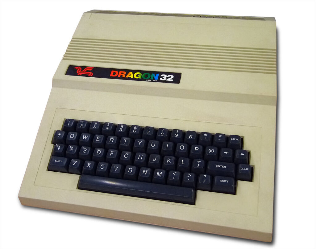
SOUND AND COLOUR FAULTS
A. No Picture or Sound
1. Check transformer.
2. Check power supply circuit board.
(a) Check PL10
(b) Test voltages
(c) Check diodes.
3. Check RESET button operation.
4. Check IC15 properly seated.
5. Replace IC15.
B. No Sound
1. Check TV channel timing.
2. Retune modulator.
3. Change IC20.
C. Faulty Colour
1. Adjust RV1 (and RV2 if fitted).
2. Alter value of C7.
3. To obtain full green screen or to cure ‘rainbow effect’, fit a 2-22 pf capacitor trimmer instead of C7.
4. If colour fault on 22″ or 27″ SONY sets, then fit 15K resistor across Pin 4 of IC9 to Pin 4 of IC10.
5. Change IC9.
6. Change IC16.
7. Change IC12.
D. Garbage on Screen
1. If RESET switch cures fault, then change IC17.
2. Change IC15.
3. Change IC17.
4. Change IC18.
JOYSTICK FAULTS
Using a known good joystick, check operation with diagnostic cartridge. Ensure both joysticks are used.
1. Change IC20.
2. Change IC25.
3. Check R1, R57, R58, R59, R60, R61, R62.
CARTRIDGE FAULTS
1. Check for blockage of cartridge port.
2. Check cartridge guides in correct sides and secure.
3. Check address lines from port to IC15, IC19 and IC26/35.
4. Change IC 15.
PRINTER FAULTS
1. Check connection lead correctly wired and that printer has automatic line feed.
2. Check keyboard operation.
3. Change IC24.
FAULTS DURING PROGRAM OPERATION
1. Check program is valid – test with other program.
2. Change IC15.
3. Change IC17.
4. Change IC18.
5. Change IC19.
6. Check RAM lines.
CASSETTE FAULTS
Using a cassette recorder and lead known to work successfully with the Dragon 32, save and load a small program. If successful, then the problem is likely to be cassette-computer mismatch.
1. Check lead from computer to cassette internally for short or open circuit.
2. If MOTOR ON/OFF function is at fault, try pulling 2.5mm jack out slightly.
3. Check cassette output signal level is at least 1V positive and 0.5V negative with respect to ground.
4. To limit signal from cassette to computer, fit resistor (270-470R) in series with cassette input. This can be done by cutting the track to Pin 4 of the tape socket and bridging with the resistor.
5. Check that recorder does not distort waveform (i.e. worn or dirty lead).
6. Remove Mic lead when loading and Ear lead when saving.
7. Do not have TV too close to computer.
If the problem appears to be with the computer:
1. Check relay operation and diode D1 2. Change IC20.
3. Change IC25. 4. Change IC34.
Problems can also be experienced using cassette recorders fitted with ALC (Automatic Level Control) due to the response time of the circuit. This can usually be overcome by using the following program to save programs in memory. The cassette recorder should be set up to record and the following entered as one line:
MOTOR ON: SOUND 120;50 : FOR N = 1 TO 100 : NEXT: CSAVE “Program Name”
This has the effect of allowing the ALC to settle down prior to the output of data from the computer.


